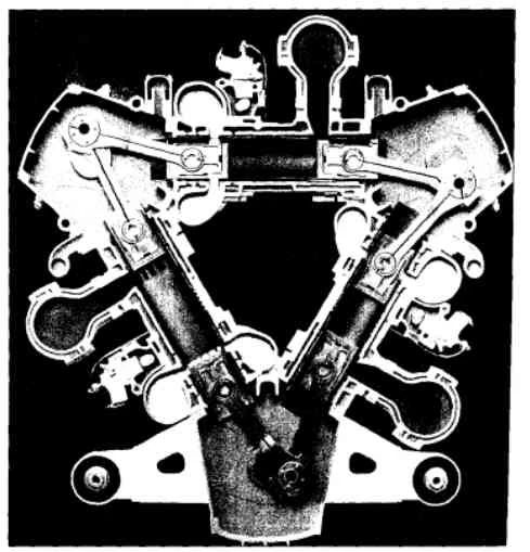
Half slice of an engine with a Napier Deltic configuration
The Napier Deltic engine is a British opposed-piston valveless, two-stroke diesel engine used in marine and locomotive applications, designed and produced by Napier & Son. The cylinders were divided in three blocks in a triangular arrangement, the blocks forming sides with crankcases located in each apex of the triangle.
The term Deltic (meaning in the form of the Greek letter Delta) is used to refer to both the Deltic E.130 opposed-piston high-speed diesel engine and the locomotives produced by English Electric using these engines, including its demonstrator locomotive named DELTIC and the production version for British Railways, which designated these as (TOPS) Class 55. A single half-sized, turbocharged Deltic power unit also featured in the English Electric-built Type 2 locomotive, designated as the Class 23. Both locomotive and engine became better known as the "Baby Deltic".
History and design[]
The Deltic story began in 1943 when the British Admiralty set up a committee to develop a high-power, lightweight Diesel engine for Motor Torpedo Boats. Hitherto in the Royal Navy, such boats had been driven by petrol engines, but this fuel is highly flammable, making them vulnerable to fire, and at a disadvantage compared with the German Diesel-powered E-boats.
Until this time, Diesel engines had poor power-to-weight ratio and low speed. Before the war, Napier had been working on an aviation Diesel design known as the Culverin after licensing versions of the Junkers Jumo 204. The Culverin was an opposed-piston two-stroke design. Instead of each cylinder having a single piston and being closed at one end with a cylinder head, the Jumo-based design used an elongated cylinder containing two pistons moving in opposite directions towards the centre. This negates the need for a heavy cylinder head, as the opposing piston filled this role. On the downside, the layout required separate crankshafts on each end of the engine, and some form of gearing to take off power and combine it back into a single shaft. The primary advantage of the design was that it led to a rather "flat" engine, intended to be buried in the wings of large aircraft.
The Admiralty required a much more powerful engine, and knew about Junkers' designs for multi-crankshaft engines of straight six and diamond-form. The Admiralty felt that these would be a reasonable starting point for the larger design which it required. The result was a triangle, the cylinder banks forming the sides, and tipped by three crankshafts, one at each apex. The crankshafts were connected with phasing gears to drive one output shaft. In this arrangement, there were six banks of pistons driving three crankshafts, the same as three separate V-engines of the same overall size. Various models of Deltic engine could be produced with varying numbers of cylinders, though nine and eighteen cylinders were the most common, having three and six cylinders per bank respectively. In 1946, the Admiralty placed a contract with the English Electric Company, parent of Napier, to develop this engine.
One feature of the engine was the way that crankshaft-phasing was arranged to allow for exhaust port lead and inlet port lag. These engines are called "uniflow" designs, because the flow of gas into and out of the cylinder is one way, assisted by mild supercharging to improve cylinder exhaust scavenging. The inlet/outlet port order is In/Out/In/Out/In/Out going around the triangular ring (i.e. the inlet and outlet manifold arrangements have C3 rotational symmetry).
Earlier attempts at designing such an engine met with the difficulty of arranging the pistons to move in the correct manner, for all three cylinders in one delta, and this was the problem which caused Junkers Motorenbau to leave behind work on the delta-form while continuing to prototype a diamond-form four-crankshaft 24-cylinder Junkers Jumo 223. Mr. Herbert Penwarden, a senior draughtsman with the Admiralty Engineering Laboratory, suggested that one crankshaft needed to revolve anti-clockwise to achieve the correct piston-phasing, so Napier designers produced the necessary gearing in order that one of them rotated in the opposite direction to the other two.
Being an opposed-piston design with no inlet or exhaust valves, and no ability to vary the port positions, the Deltic design arranged each crankshaft to connect two adjacent pistons operating in different cylinders in the same plane, using "fork and blade" connecting rods, the latter an "inlet" piston used to open and close the inlet port, and the former an "exhaust" piston in the adjacent cylinder to open and close the exhaust port. This would have led the firing in each bank of cylinders to be 60 degrees apart. However, it was decided to arrange that each cylinder's exhaust piston would lead its inlet piston by 20 degrees of crankshaft rotation. This allowed the exhaust port to be opened well before the inlet port, and allowed the inlet port to be closed after the exhaust port, which led to both good scavenging of exhaust gas, and good volumetric efficiency for the fresh air charge. This required the firing events for adjacent cylinders to be 40 degrees apart. For the 18 cylinder design, it was possible for firing events to be interlaced over all six banks. This led to the even, buzzing exhaust note of the Deltic, with a charge ignition every 20 degrees of crankshaft revolution, and a lack of torsional vibration, ideal for use in mine-hunting vessels. It should be noted that the 9 cylinder design, having three banks of cylinders, has its crankshafts rotating in the opposite direction. The exhaust lead of 20 degrees is added to the 60 degrees between banks giving firing events for adjacent cylinders in the same bank 80 degrees apart. By interlacing firing events over all three banks of cylinders, this still leads to an even buzzing exhaust note, charge ignition occurring every 40 degrees of crankshaft revolution with consequent reduction of torsional vibration.
Although the engine was cylinder-ported and required no poppet valves, each bank had a camshaft, driven at crankshaft speed. This was used solely to drive the fuel injection pumps, each cylinder having its own injector and pump, driven by its own cam lobe.
Uses[]
[]
Development began in 1947 and the first Deltic unit was produced in 1950. By January 1952 six engines were available, enough for full development and endurance trials. S212, a captured ex-German E-Boat powered by three Mercedes-Benz Diesel engines, was selected for these trials, since its power units were of approximately equal power to the new 18-cylinder Deltic engines. Two of the three Mercedes-Benz engines were replaced with Napier Deltics, the compactness of the Deltic being graphically illustrated: they were half the size of the original engines. The Deltic weighed one fifth of its contemporaries of equivalent power.
Proving successful, Deltic Diesel engines became a common power plant in small and fast naval craft. The Royal Navy used them first in the fast attack craft. Subsequently they were used in a number of other smaller attack craft. The low magnetic signature lent itself to use in mine countermeasures vessels and the Deltic was selected to power the Ton class minesweeper. The Deltic engine is still in service in the Hunt class mine countermeasures vessel. These versions are de-rated to reduce engine stress.
Deltic Diesels served in MTBs and PT boats built for other navies. Particularly notable was the Norwegian Tjeld or Nasty class, which was also sold to Germany, Greece, and the United States Navy. Nasty class boats served in the Vietnam War, largely for covert operations.
Smaller nine-cylinder Deltic 9 engines were used as marine engines, notably by minesweepers. The Ton class vessels were powered by a pair of Deltic 18s and used an additional Deltic 9 for power generation for their magnetic influence sweep. The Hunt class used three Deltic 9s, two for propulsion and again one for power generation, but this time with a hydraulic pump integrated as well to power bow-thrusters for slow-speed manoeuvring.
Railway use[]
The "Deltic" engines were used in two types of British rail locomotive: classes 55 and 23, built in the 1960s. Because of their engines, these types were nicknamed "Deltics" and "Baby Deltics" respectively.
The Class 55 used two D18-25 series II type V Deltic engines: mechanically-blown 18-cylinder engines each rated at 1650 hp continuous at 1500rpm. The Class 23 used a single less powerful (but more power per cylinder because of the turbocharger) nine-cylinder turbocharged T9-29 Deltic of 1100 hp.
Reliability in service[]
While the Deltic engine was successful and very powerful for its size and weight, it was a highly-strung unit, requiring careful maintenance. This led to a policy of unit replacement rather than repair in situ. Deltic engines were easily removed after breakdown, generally being sent back to the manufacturer for repair, although after initial contracts expired both the Royal Navy and British Railways set up their own workshops for overhauls.
Turbo-compound Deltic[]
The "E.185" or "Compound Deltic" turbo-compound variant was planned and a single prototype was built in 1956 and tested in 1957. This capitalised on Napier's experience with both the "Nomad", and its increasing involvement with gas turbines. It used the Deltic as the gas generator inside a gas turbine, with both a twelve-stage axial compressor and a three stage gas turbine. Unlike the Nomad, this turbine was not mechanically coupled to the crankshaft, but merely drove the compressor. It was hoped that it would produce 6,000 horsepower, with fuel economy and power-to-weight ratio "second to none".
Predictions by the engineers closely connected with it were that connecting rod failure would be the limit on this power, failing at around 5,300 bhp. On test it actually produced 5,600 bhp before throwing a connecting rod through the crankcase just as predicted. Naval interest had waned by 1958 in favour of the pure gas turbine, despite its heavier fuel consumption, and no further development was carried out.
See Also[]
| Piston engine configurations | |
|---|---|
| Type | Bourke • Controlled combustion • Deltic •Orbital • Piston • Pistonless (Wankel) • Radial • Rotary • Single • Split cycle • Stelzer • Tschudi |
| Inline types | H · U · Square four · VR · Opposed · X |
| Stroke cycles | Two-stroke cycle • Four-stroke cycle • Six-stroke cycle |
| Straight | Single · 2 · 3 · 4 · 5 · 6 · 8 · 10 · 12 · 14 |
| Flat | 2 · 4 · 6 · 8 · 10 · 12 · 16 |
| V | 4 · 5 · 6 · 8 · 10 · 12 · 16 · 20 · 24 |
| W | 8 · 12 · 16 · 18 |
| Valves | Cylinder head porting • Corliss • Slide • Manifold • Multi • Piston • Poppet • Sleeve • Rotary valve • Variable valve timing • Camless |
| Mechanisms | Cam • Connecting rod • Crank • Crank substitute • Crankshaft • Scotch Yoke • Swashplate • Rhombic drive |
| Linkages | Evans • Peaucellier–Lipkin • Sector straight-line • Watt's (parallel) |
| Other | Hemi • Recuperator • Turbo-compounding |
External links[]

|
This page uses some content from Wikipedia. The original article was at Napier Deltic. The list of authors can be seen in the page history. As with Autopedia, the text of Wikipedia is available under the GNU Free Documentation License. |